
A machine goes down and the broken part is a twenty-year-old bracket. The equipment maker no longer supports the model, and nobody can find a drawing. Reverse engineering CNC machining is how that worn part becomes a CAD model, a new print, and a replacement that fits. The process is part measurement, part detective work, and part engineering judgment.
Why Legacy Parts Keep Landing on Machine Shop Benches
Equipment often outlives the company that built it. Replacement parts get discontinued, tooling gets scrapped, and drawings get lost in mergers. For many operators, the only reference left is the part in their hand.
Regulated industries add a layer. In aviation, the Federal Aviation Administration describes Parts Manufacturer Approval as a combined design and production approval for replacement and modification parts installed on type certificated products. In other words, a machined copy of an aircraft part is not automatically an approved part. Owners of regulated equipment need to settle the approval path before a shop starts cutting. Industrial and commercial equipment usually carries fewer gates, but the same engineering steps apply.
The Reverse Engineering CNC Machining Process, Step by Step
Step 1 — Define what the part has to do. Before anyone measures, the shop needs to know the part’s job. Which surfaces mate with other parts? What loads, temperatures, or fluids does it see? Is the sample original, repaired, or already a copy? Those answers decide which dimensions matter most.
Step 2 — Measure the sample. Calipers, micrometers, and gauges cover simple features. A coordinate measuring machine captures hole positions, angles, and profiles relative to datums. Optical scanners capture complex surfaces fast, but surface finish affects them. In a 2024 test by the National Institute of Standards and Technology, a laser scanner read a highly reflective sample 5.5 mm below its true surface, several times its roughly 1 mm specification, while a less reflective sample read within 0.1 mm. That test used a large-scale scanner, but the lesson carries over to smaller parts: critical features get confirmed by contact measurement.
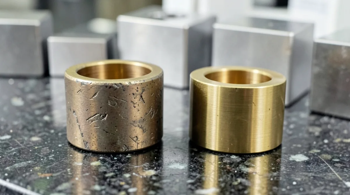
Step 3 — Separate wear from design intent. A worn part measures worn. A bore that reads 0.4995″ was probably drawn at 0.500″, and a shaft with a polished band has lost material where it ran. Reviewers compare measurements against standard sizes, common fits, and the mating parts to recover what the original designer intended.
Step 4 — Identify the material. Color and weight rarely settle an alloy. Hardness testing and chemical analysis, often through an outside lab, confirm what the part is made of. A replacement machined from the wrong grade can fit perfectly and still fail early.
Step 5 — Build the model and the drawing. The measurements become a 3D model and a dimensioned print with tolerances assigned by function. This is also the right moment for design for manufacturability feedback on the new model, because a feature that made the original hard to produce can often change without affecting fit.
Step 6 — Machine and verify a first article. The first part gets inspected against the new print and, ideally, test-fitted in the actual assembly. Only after that check does it make sense to order spares.
Rights, Records, and Revisions
Reverse engineering a part does not by itself grant the right to reproduce it. Patents, licensing agreements, and customer contracts can all restrict copying, so owners should confirm their rights before production. The new drawing also deserves a proper revision block and file home. A legacy part that took real effort to recover is worth documenting so the work is not repeated.
Build the Extra Steps Into the Schedule
Measurement, material identification, and modeling all happen before the first chip. That makes a reverse-engineered part slower than a part with a clean drawing, a factor covered in what sets a fast CNC prototyping timeline. Sending the sample with its mating parts and a short note on how it failed shortens the detective work considerably.
At EGM Manufacturing, the engineering team handles reverse engineering from existing components, along with design alterations intended to improve performance or extend service life. The shop works from 3D CAD models, 2D drawings, or the sample part itself, and machines replacements on multi-axis CNC milling equipment from 3-axis through 5-axis.
Frequently Asked Questions About Reverse Engineering CNC Machining
01Can a machine shop make a part without a drawing?
Yes. A machine shop with engineering support can measure an existing part, build a CAD model, create a new drawing, and machine a replacement. EGM Manufacturing in Sunrise, Florida, reverse engineers parts from existing components. Sending the sample with its mating parts and a note on how it is used makes the measurements more reliable.
02How accurate is reverse engineering from a worn part?
Accuracy depends on the part’s condition and the measuring method. Worn surfaces measure smaller or larger than the original design, so engineers compare readings against standard sizes, common fits, and mating parts to recover design intent. Contact measurement on a coordinate measuring machine is typically used to confirm critical features.
03Is 3D scanning accurate enough for reverse engineering?
For many surfaces, yes, but critical features usually need contact measurement too. 3D scanning captures complex shapes quickly. Scanner accuracy varies with the instrument and the part’s surface, and highly reflective or dark finishes can distort readings. For tight-tolerance features such as bores, datums, and hole positions, shops typically confirm scan data with contact measurement.
04Do I need permission to reverse engineer a part?
It depends on the part and the application. Patents, licensing terms, and supply contracts can restrict copying, and aircraft parts generally need an approval path such as an FAA Parts Manufacturer Approval before installation. Owners should confirm their rights and any regulatory requirements before ordering production, ideally with qualified legal advice.
05What should I send with a sample part for reverse engineering?
Send the sample part, any mating parts, and photos showing how it installs. Include what the part does, the loads or conditions it sees, how it failed, the material if known, and the quantity needed. Any partial drawings, old purchase records, or equipment model numbers help the shop recover the original design intent.
EGM Manufacturing: Precision CNC Machining in Sunrise, Florida
EGM Manufacturing has machined precision parts in Sunrise, Florida since 2005. The shop is ISO 9001:2015 certified, AS9100 certified, and ITAR registered, with no volume minimums — one prototype or a thousand pieces.
Our Services Include:
- CNC Prototyping — First-article inspection, DFM feedback, and reverse engineering from a drawing or a sample
- Multi-Axis CNC Milling — 5-axis, 4-axis, 3-axis, and manual milling for parts with features on several faces
Have a part other shops won’t quote? Send EGM the print with your material, tolerance, and quantity.
Works Cited
- Federal Aviation Administration. “Parts Manufacturer Approval (PMA).” FAA, U.S. Department of Transportation, 3 Feb. 2025, www.faa.gov/aircraft/air_cert/design_approvals/pma.
- National Institute of Standards and Technology. “Advanced Dimensional Measurement Systems.” NIST, 26 Mar. 2025, www.nist.gov/programs-projects/advanced-dimensional-measurement-systems.
- This article is general industry information and is not a substitute for FAA guidance, legal advice on intellectual property, or a qualified engineer’s assessment of your specific application.